DATA FLOW DIAGRAM (DFD)
A data-flow diagram (DFD) is a graphical representation of the "flow" of data through an information system. It differs from the flowchart as it shows the data flow instead of the control flow of the program.
DFD usually use to figured a system division into smaller module and can make user to easy that insufficiently understand computer area for understands system who will be worked. A data-flow diagram can be used for the visualization of data processing (structured design).
Although DFD have excess, that is can depict system structure with devided become lower level (decomposition), can show data flow in system, can depict parallel process in system, can show data deposit, can show external entity, but DFD have limitation too.
Limitation of DFD such as:
- DFD not show looping process(loop)
- DFD not show decision process
- DFD not show calculation process
Context DiagramContext Diagram is a supreme level from DFD to figured all input to or from system. its consisted of one process and figured scope for a system. its will give picture about overall of system. System limited by boundary ( can be depicted with broken line). In context diagram just one process. There may not store in context diagram .Context Diagram contain public picture(marginally) for system development.
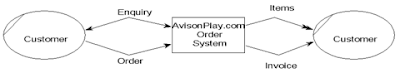
picture of context diagram
Zero Diagram
Zero Diagram is a diagram to describe process of data flow diagram. Zero Diagram is Providing views on the overall system in which, showing the main function or process that is, the flow of data and external entity.in this level may be existence storage data. For process which not detailed again in next level added by symbol ‘*’ or ‘ P’ in the end process number. Input balance and output ( balancing) between diagram 0 with context diagram have to be maintain.
Detail Diagram
Detail Diagram is a Diagram to describe process in zero diagram or high level.
 Numbering level on DFD can be seen on table hereunder: In one level shall not there are more than 7 process and maximal 9, if more must be done decomposition.
Process Specification
Each process in DFD must have the process specification. in top level method used to describe process by using descriptive sentence. At more level detailed that is under process (functional primitive) required the specification structure.Process Specification will become guide to programmer in coding. Method used in the process specification : * description process in the story * decision table * decision tree
SYMBOL in DFD:
- External entity
- Data Flow
- Process
- Data Store
External Entity
Something in outside system, but its give data into system or give data for system, symbol with a notation box. External entity not include of part system. When information system designed to one part then other part which still related become external entity. Guide of External Entity name:
- terminal name is noun
- Terminal may not have the same name except the same objects
Data Flow
Data flow is a Place for information stream. Data flow symbol with straight line to connective component of system. Data flow direction is indicated with arrows and lines give the name on the flow of data that flows. Flow data flow between processes, data storage and data flow indicates that the form of data input for the system.
Guide of Data Flow name:
- Name of data flow which consist of some word flow attributed with continued line.
- There may not be any data flow which its same name and gift of name have to express its contents
- Data stream which consist of some element can be expressed with element grup
- Avoid usage of word ‘ data’ and ‘ information’ to give the name at data flow
- As possible the name of data flow written is complete
Other rule:
- Data flow name which turn in at a process may not same by the name of secretary data flow of that process.
- Data flow into or out of data storage doesn't need to give a name if:
- The flow of data simple and easy to understand
- Describes the data flow of all data items
- There may not any data flow of terminal to data storage or on the contrary because terminal isn't part of system, terminal relation with data storage have to pass process.
Process
Process is what's done by system. Process can processed data or data flow to become exit data stream. Function of process is transformation one or some input data become one or some output data as according to specification. Each process have one or some input and also result one or some output data. Process usually calling by bubble. Guide of process name:
- Name of process consist of noun and verb
- Don't use word process as part of the process name
- May not have some process that has the same name
- Process must to give number. Number sequence as possible follow process sequence or stream, but that way meaningless number sequence absolutely represent sequence process by chronologically.
Data Store
Data store is storage place for data that exists in the system. Data store symbol with couple two parallel line or two line wrongly one side from other side openly. Process can take data from or give data to database.
Guide of Data Store name:- The name should reflect the data storage
- When his name more than one word must be marked with the number
DFD Symbol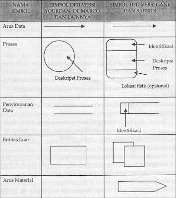
 Data Dictionary
Data dictionary is a reserved space within a database which is used to store information about the database itself. Data dictionary is also called with a system data dictionary is a catalog of facts and data information needs of an information system. In function to help system agent to interpreting application in detail and organization all of data element that utilized by system exactly so user and system analyst have same understanding basic about entry, output, storage and process. In analysis phase, data dictionary used as communication between system analyst with user. in development system phase, data dictionary used to design input, and report database. Data flow in DFD have the character of globally, boldness more detailed can be seen in data dictionary.
Data dictionary load the followings :
- Name of data current: must note that readers who need further explanation about a flow of data can find it easily
- Alias: alias or other name of the data can be written when there is
- Forms of data: used to segment the data dictionary to use when designing the system
- Flow data: indicates from which data flows and where the data
- Description: to give an explanation of the meaning of the data flow
Balancing in DFDData flow into and out of a process must be the same as the flow of data into and out of the details of the process on the level / levels below. Name of the data flow into and out of the process must match the name of the flow of data into and out of the details of the process. Number and the name of an entity outside the process must be equal to the number of names and entities outside of the details of the process.
Things which must be gave attention to DFD owning than one level:- There are must input balance and output between one level and level next
- Balance between level 0 and level 1 seen at input / output of data stream to or from terminal in level 0, while balance between level 1 and level 2 seen at input / output of data stream to/from pertinent process
- Data flow name, data of storage terminal and every level must be same if its same object
Prohibition in DFD
- Data flow may not from external entity directly to wend another external entity without passing a process.
- Data flow may not from direct data deposit go to external entity without passing a process
- Data flow may not from direct data deposit go to other data deposit without passing a process
- Data flow from one direct process go to other process without passing a data deposit better possible avoided.
References:- Slide Part 4 - DATA FLOW DIAGRAM by ER Ngurah Agus Sanjaya
- HM, Jogiyanto. 2007. Analisis & Desain Sistem Informasi. Yogyakarta: ANDI.
-
Al-Bahra Bin Ladjamudin, Analisis dan Desain Sistem Informasi, Graha Ilmu


 Dimana :